UART(Universal Asynchronous Receiver/Transmitter,通用异步收/发器)
s3c2440A 提供了三个UART端口,它们都可以通过查询、中断和DMA方式传输数据,而且每个UART都分别有一个64个字节的接收FIFO和一个64个字节的发送FIFO。
OVERVIEW
The UART can generate an interrupt or a DMA request to transfer data between CPU and the UART. The UART can support bit rates up to 115.2K bps using system clock. If an external device provides the UART with UEXTCLK, then the UART can operate at higher speed.
The S3C2440A UART includes programmable baud rates, infrared (IR) transmit/receive, one or two stop bit insertion, 5-bit, 6-bit, 7-bit or 8-bit data width and parity checking(奇偶校验).
Each UART contains a baud-rate generator, transmitter, receiver and a control unit.The transmitter and the receiver contain 64-byte FIFOs and data shifters. Data is written to FIFO and then copied to the transmit shifter before being transmitted. The data is then shifted out by the transmit data pin (TxDn). Meanwhile, received data is shifted from the receive data pin (RxDn), and then copied to FIFO from the shifter.
FEATURES
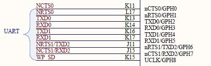
— RxD0, TxD0, RxD1, TxD1, RxD2, and TxD2 with DMA-based or interrupt-based operation
— UART Ch 0, 1, and 2 with IrDA 1.0 & 64-byte FIFO
— UART Ch 0 and 1 with nRTS0, nCTS0, nRTS1, and nCTS1(UART2 没有 nRTS、nCTS,所以它不支持 AFC)
— Supports handshake transmit/receive
UART 数据帧
UART是串行异步通信方式,通信过程中每次只能传输一位(1 bit),若干位组成一个数据帧(frame)。帧是 UART 通信中最基本单元,它主要包含:开始位、数据位、校验位(不是必须的)、停止位。
Data Transmission
The data frame for transmission is programmable. It consists of a start bit, 5 to 8 data bits, an optional parity bit and 1 to 2 stop bits, which can be specified by the line control register (ULCONn). The transmitter can also produce the break condition(中止条件), which forces the serial output to logic 0 state for one frame transmission time(相当于产生一个内容为零的数据帧). This block transmits
break signals after the present transmission word is transmitted completely. After the break signal transmission, it continuously transmits data into the Tx FIFO (Tx holding(保持/持有) register in the case of Non-FIFO mode).
Data Reception
Like the transmission, the data frame for reception is also programmable. It consists of a start bit, 5 to 8 data bits, an optional parity bit and 1 to 2 stop bits in the line control register (ULCONn). The receiver can detect overrun error(溢出错误), parity error, frame error and break condition, each of which can set an error flag.
— The overrun error indicates that new data has overwritten the old data before the old data has been read.
— The parity error indicates that the receiver has detected an unexpected parity condition.
— The frame error indicates that the received data does not have a valid stop bit.
— The break condition indicates that the RxDn input is held in the logic 0 state for a duration longer than one frame transmission time.(RxDn 输入端口保持逻辑0持续长于一个数据帧的传输时间)
Receive time-out condition occurs when it does not receive any data during the 3 word time (this interval follows the setting of Word Length bit) and the Rx FIFO is not empty in the FIFO mode.
Auto Flow Control (AFC)
The S3C2440A's UART 0 and UART 1 support auto flow control with nRTS and nCTS signals. In case, it can be connected to external UARTs. If users want to connect a UART to a Modem, disable auto flow control bit in UMCONn register and control the signal of nRTS by software. In AFC, nRTS depends on the condition of the receiver and nCTS signals control the operation of the transmitter. The
UART's transmitter transfers the data in FIFO only when nCTS signals are activated (in AFC, nCTS means that other UART's FIFO is ready to receive data). Before the UART receives data, nRTS has to be activated when its receive FIFO has a spare more than 32-byte and has to be inactivated when its receive FIFO has a spare under 32-byte (in AFC, nRTS means that its own receive FIFO is ready to receive data).
Baud-rate Generation
Each UART's baud-rate generator provides the serial clock for the transmitter and the receiver. The source clock for the baud-rate generator can be selected with the S3C2440A's internal system clock(PCLK、FLCK/n )or UEXTCLK. In other words, dividend(被除数) is selectable by setting Clock Selection of UCONn. The baud-rate clock is generated by dividing the source clock (PCLK, FCLK/n or UEXTCLK) by 16 and a 16-bit divisor specified in the UART baud-rate divisor register (UBRDIVn). The UBRDIVn can be determined by the following expression:
UBRDIVn = (int)( UART clock / ( buad rate x 16) ) –1 -------> baud_rate = (int)(UART_clock/((UBRDIVn + 1) * 16)) //这里的 +1 是为了防止分母为零
( UART clock: PCLK, FCLK/n or UEXTCLK )
Where, UBRDIVn should be from 1 to (216-1), but can be set 0 (bypass mode) only using the UEXTCLK which should be smaller than PCLK.
For example, if the baud-rate is 115200 bps and UART clock is 40 MHz, UBRDIVn is:
UBRDIVn = (int)(40000000 / (115200 x 16) ) -1 = (int)(21.7) -1 [round to the nearest whole number(四舍五入为一个整数)] = 22 -1 = 21
Baud-Rate Error Tolerance
UART Frame error should be less than 1.87%(3/160).
tUPCLK = (UBRDIVn + 1) x 16 x 1Frame / PCLK tUPCLK: Real UART Clock
tUEXACT = 1Frame / baud-rate tUEXACT: Ideal UART Clock 、、这里的 1frame 是指,一个数据帧的长度(以位计)
UART error = (tUPCLK – tUEXACT) / tUEXACT x 100%
NOTES
1. 1Frame = start bit + data bit + parity bit + stop bit.
2. In specific condition, we can support the UART baud rate up to 921.6K bps. For example, when PCLK is 60MHz, you can use 921.6K bps under UART error of 1.69%.
UART 特殊寄存器
( 1) UART 线性控制寄存器(ULCONn):R/W 用于规定数据帧的格式
( 2) UART 控制寄存器(UCONn)
( 3) UART FIFO 控制寄存器(UFCONn)
( 4) UART MODEM 控制寄存器(UMCONn) :R/W 串口 MODM控制寄存器,AFC 使能控制等
( 6) UART 错误状态寄存器(UERSTATn)
( 7) UART FIFO 状态寄存器(UFSTATn)
( 8) UART MODEM 状态寄存器(UMSTATn)
( 9) UART 发送缓存寄存器(UTXHn) :W 串口发送缓存寄存器,用于表示发送的数据(只写,按字节方式)
#defineUTXH0 (*(volatile unsignedchar *)0x50000020)
(10) UART 接收缓存寄存器(URXHn) :R 串口接收缓存寄存器,用于读取串口的数据(只读,按字节方式)
#defineURXH0 (*(volatile unsigned char *)0x50000024)
( 5) UART 接收发送状态寄存器(UTRSTATn) :R 串口发送/接收状态寄存器,保存着相应通道的接收和发送状态
(11) UART 波特率除数寄存器(UBRDIVn):R/W 波特率除数寄存器
//要实现简单通信,只需使用串口的三个引脚:TXDn、RXDn、GND(接地,这里不用设置)
/* GPIO registers */ //GPH2,GPH3 used as TXD0,RXD0
#defineGPHCON (*(volatile unsigned long *) 0x56000070)
#defineGPHDAT (*(volatile unsigned long *) 0x56000074)
#defineGPHUP (*(volatile unsigned long *) 0x56000078)
#define nGPHCON 0xa0 //GPH2、GPH3 使用他们的复用功能,都设置为10 (1010,0000)
#define nGPHUP 0x0 //使能上拉电阻,以稳定电平信号,保障数据传输的正确。